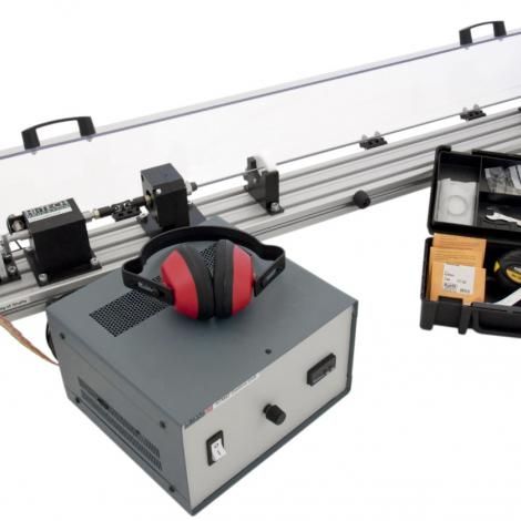
The modes of oscillation and resonance of rotors, with continuous mass distribution, can be clearly demonstrated using this bench top unit.
The speed control of the motor can be finely adjusted to view a shaft as it reaches and goes through its critical speed modes.
A sturdy extruded frame is the base for the driving motor, self-aligning bearings, optional roller bearings (for fixed end condition setups), safety/ guide rings and test shafts.
There is a safety micro-switch which ensures that the guard must be down for testing to commence.
By using of thin, elastic rotor shafts, made of high-strength steel, the oscillatory phenomena can be easily understood and demonstrated. Some configurations also allow the second mode of whirl to be viewed.
A variety of shaft diameters and lengths are provided for testing. The bearing end conditions can be changed, and the safety ring positions moved, to perform a wide variety of experiment configurations. Due to the slotted arrangement of the base extrusion, adjustment of the safety rings and bearing block positions can be easily changed.
Samples are made from silver steel and can be easily moved in and out of the test setup where they are fixed in place with specific collets at either end.
Because of the nature of the testing, samples can become deformed or bent, which will affect test results. They have therefore been designed to be able to be easily and cheaply removed and replaced.


