Product number: HFC14
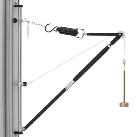
This apparatus illustrates the application of a triangle of forces very clearly through the use of a wall jib crane. This self-contained jib crane has a vertical back support that supports a vertical rod. At the bottom of this rod is attached a swivel joint for the lower compression member. This joint swivels but cannot move vertically. At the upper end of the rod is a movable joint. This joint has a hook protruding and allows the attachment of a chain which itself is attached to the tension member of the crane.
The ends of the compression and tension member are joined at a common point. A small pulley is attached at this point also, over which a cord passes, and terminates with the Load hanger. One end of the cord also attaches to a movable hook that runs vertically on the support rod.
By adjusting the cord length, chain length and positions of the hooks, the lengths of the compression and tension members can be adjusted along with their angular positions.
The forces in the compression member are read directly from the integral Newton scale. A compression spring of known spring rate is enclosed within the compression member. A spring balance is suspended between the chain and the pulley to measure the tensile forces in the tension member. After loading the member lengths can be adjusted to their ‘zero load’ lengths as part of the experimental procedure.

Specifications and resources
Maximum vertical distance between wall pivots approximately 350mm
Tensile Member length: 500mm (approx.)
Compressive Member length: 400mm (approx.)
Tensile force spring balance 6Kgf in 0.1Kgf increments
Compressive force spring balance: 60N in 2N increments
Weights set: 3 x 5N
1 x Load hanger

